Business Solutions and Lean Systems Engineering

Business Solutions and Lean Systems Engineering is one of the Five Core Competencies of the Lean enterprise.

The Business Solutions and Lean Systems Engineering competency describes how to apply Lean-Agile principles and practices to the specification, development, deployment, and evolution of large, complex software applications and cyber-physical systems.

Introduction

Humanity has always dreamed big and scientists, engineers, and developers turn those big dreams into reality. Realizing big dreams requires innovation, experimentation, and knowledge from many diverse disciples. Engineers lead the creation of these big ideas by defining and coordinating all the activities necessary to successfully specify, design, test, deploy, evolve, and ultimately decommission large, complex solutions. That includes:

  • Requirements analysis
  • Business capability definition
  • Functional analysis and allocation
  • Design synthesis
  • Verification and validation (V&V)
  • Design alternatives and trade studies
  • Modeling and simulation

As they build and deploy ever-larger applications—in increasingly complex, connected, and unpredictable environments—systems and software engineers, architects, designers, developers, testers, and others face even more significant challenges. This competency describes the critical practices to build large, complex, cyber-physical systems, as well as the world’s most significant IT business solutions. Most cyber-physical systems are driven by significant, backend, IT solutions that run their operations. Figure 1 shows an autonomous delivery solution example that includes both the business and vehicle architectures. The principles and practices presented here apply to both, expressed as a single competency.

Why Business Solutions and Lean Systems Engineering?
Historically, approaches to building large solutions have taken a sequential, stage-gated approach to development. Work is planned and broken-down upfront into detailed requirements with a pre-determined fixed schedule and budget for the entire lifecycle. Large teams often worked in isolation on ‘their part of the system.’ Progress was checked periodically through phase-gate milestones. The first time an end-to-end integration occurred was towards the end of the lifecycle, leaving little time—or budget—to adjust.
As a result, large solutions may have waited years before receiving any user feedback, have had engineers retire before the system builders implemented their specifications, and have specified components that became obsolete before the system was ever deployed. It’s no wonder that many large systems are deployed late, over budget, and with unpredictable capabilities and quality. This usually results in higher than expected maintenance and operations expense, lower profits, and other business problems. Lean enterprises employ a fresh approach to building these large solutions.
Instead, the Scaled Agile Framework® (SAFe®) organizes the activities of building large-scale solutions in a flow-based, value delivery-focused model, driven by Lean and Agile principles. The framework provides nine Lean-Agile principles to guide system builders to more effective outcomes:
  • Principle #1 – Take an economic view
  • Principle #2 – Apply systems thinking
  • Principle #3 – Assume variability; preserve options
  • Principle #4 – Build incrementally with fast, integrated learning cycles
  • Principle #5 – Base milestones on objective evaluation of working systems
  • Principle #6 – Visualize and limit WIP, reduce batch sizes, and manage queue length
  • Principle #7 – Apply cadence; synchronize with cross-domain planning
  • Principle #8 – Unlock the intrinsic motivation of knowledge workers
  • Principle #9 – Decentralize decision-making
These principles apply directly to the development of all kinds of large and complex systems. We depend on them to support our values, mindset, and decision-making throughout the system’s lifecycle. A brief explanation of how these principles apply to the largest and most complex systems is provided below.
  • Principle #1 uses economics to drive all decisions and ensures we include all relevant parameters in the decision process: development costs, production costs, delivery cycle time, value delivered, etc.
  • Principle #2 confirms that everyone understands and commits to the common goals of the system and that all decisions optimize the whole solution, not individual components. It also calls out our responsibility to provide solution builders with the appropriate knowledge and alignment to make good, localized decisions that optimize the whole.
  • Principle #3 tells us that exploring alternatives is an investment in knowledge creation that leads to more optimal technical decisions. Better decisions minimize the costs and delays of downstream inefficiencies and rework.
  • Principle #4 tells us to use cadence-based learning cycles to evaluate these alternatives. While Agile teams use iterations to build potentially releasable products, large systems also use increments to validate technical assumptions.
  • Principle #5 uses the demonstrable learning gained from each cycle as the only real measure of progress. Sequential, phase-gate models that value documents and specifications delay risk and assumption mitigation. Instead, measuring progress by validating technical assumptions and user acceptance via objective evidence reduces risk and provides better outcomes.
  • Principle #6 ensures fast flow and quick feedback on the learning cycles. Small batches of work—the smallest possible thing that will possibly work, with low WIP and small queues—ensure fast flow through the system.
  • Principle #7 provides a regular, predictable cadence for validating decisions and adapting to new knowledge. Regular synchronization offers the ability to align all system builders and ensures all perspectives are understood and resolved.
  • Principle #8 recognizes that knowledge workers may have fundamentally different motivations than traditional workers and that leaders of large solutions are responsible for creating an environment in which these workers can thrive.
  • Principle #9 tells us that part of that motivation is autonomy. Pushing decision-making down to teams and individuals requires our leaders to equip all solution builders with the knowledge to make productive, decentralized decisions.
Eight Practices for Building Large Solutions with SAFe
Experience has shown that these principles—and all the practices of SAFe—work extremely well when applied to building the largest software solutions and cyber-physical systems. SAFe, after all, is designed for scale. But in a large solution context, another set of practices further inform solutions builders on how to apply SAFe, which are described in Figure 2 and the sections below.
  • Figure 2. Eight practices for building large solutions with SAFe

Business Solutions and Lean Systems Engineering

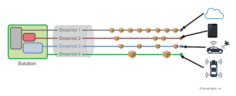
  • Figure 3. Solution trains coordinate large solution delivery

Build solution components and capabilities with Agile Release Trains
Large systems are most often decomposed by their structure (components) or behavior (capabilities) with groups of developers assigned to build their portions of the system. The Agile Release Train (ART) concept defined by Essential SAFe is already optimized to align and coordinate large groups of individuals (50-125 people) as a team-of-agile teams. Therefore, organizationally, large solutions are built by component and capability ARTs. Like Agile teams, ARTs are cross-functional, with all the skills necessary to deliver their solution. A Solution Train aligns all ARTs and ART teams on a regular cadence for planning, demonstrating, improving, and learning. SAFe defines a regular cadence within the Program Increment (PI) to integrate and demo the entire system, then adjust based on new knowledge and plan the next increment.
Build and integrate the solution with a Solution Train
Solution Trains coordinate the ARTs that build large solutions. Figure 3 shows an example Solution Train organizing the builders of the autonomous delivery solution. The Solution Train aligns all ARTs and suppliers through a shared business and technology mission.
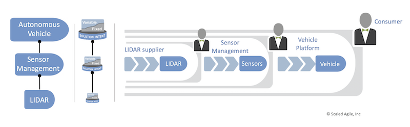
  • Figure 4. Fixed and variable solution intent and solution context

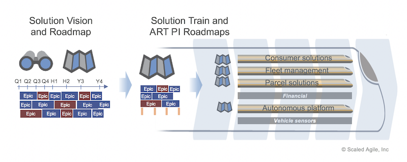
  • Figure 5. Multiple planning horizons facilitate realistic and largely localized planning

  • Figure 6. Architecture impacts the ability of the release of system elements

  • Figure 7. Supply chains with system-of-systems in SAFe

  • Figure 1.  Autonomous vehicle systems with a large-scale

        business solution and lean systems engineering aspects

To validate that ‘we’re building the right thing,’ and to verify current technical assumptions, Solution Trains integrate their product offerings at least every PI. ARTs with longer lead times (e.g., integrating packaged applications or developing hardware) should deliver incremental solutions to support early validation and learning. Software teams can provide test doubles that proxy the interface for the larger external system they are building. Hardware teams can provide dev kits, early hardware revs, simulation environments, and wooden mockups, etc.
Capture and refine system66s specifications in a fixed/ variable Solution Intent
Solution Trains need a direction, an understanding of the intended requirements and anticipated design to meet them. The Solution Intent defines the solution’s as-is and to-be specifications, serving two primary purposes:
  1. Align teams on the ‘what’ and the ‘how’ of building future (to-be) functionality
  2. Provide a record of existing requirements and design for validation and compliance concerns (as-is)
As Figure 4 illustrates, the solution intent aligns everyone in the value stream to a common view that must fit into some solution context for a customer. The context defines logical (deployment configurations) and physical (size, weight) constraints.
Traditionally, large solutions commit early to fixed and detailed specifications for the intent and context. Unfortunately, history has shown that our early specifications are often incomplete or inaccurate. What’s more, the process allows a limited opportunity for feedback and adapting to specification changes. This leads to the late discovery of issues, with no systematic way to improve them. While some requirements and design decisions should be made early (fixed requirements), many can and should be delayed (variable requirements). Economics alone must determine when exploring alternatives should stop and when decisions should become fixed. In the spirit of assume variability and preserve options, SAFe allows everything—the Solution, its Intent, and its Context—to vary during development.
At scale, creating a single source of truth for all requirements and design decisions becomes critical for aligning and coordinating all ARTs and their teams. The solution intent reduces the risk of misaligned work. It aids planning and helps ensure the delivered solution has the proper fit for use, fit for purpose, and will yield quality outcomes. SAFe’s Economic Framework also enables localized decisions on serviceability, manufacturability, unit costs, and other critical decisions, which accelerates decision-making and reduces delays. Moreover, modeling, simulation, and low-fidelity prototypes allow teams to prove out decisions and obtain feedback quicker as they iterate across multiple potential solutions in a cost-efficient manner.
Apply multiple planning horizons
Development plans for large solutions have often been defined by a fixed, hierarchical schedule that breaks down work and attempts to coordinate teams by early task assignment. In practice, these detailed schedules quickly diverged due to many circumstances—technical discoveries, gaps in specifications, and new understanding from customers. The ‘plan was not the actual,’ and rigid, detailed, long-range plans hindered the ability to adjust. In contrast, ARTs and teams use Backlogs and Roadmaps to manage work and forecast the current understanding of the schedule. As new knowledge becomes available, items can be added, changed, removed, and reprioritized to ensure delivery of the most value per increment.
SAFe’s Roadmap describes the need for multiple planning horizons. The Solution Roadmap provides a multi-year product vision while the PI Roadmap estimates nearer-term capabilities and milestones. As shown in Figure 5, Solution Trains are responsible for the long-term Vision (2-5 years) and near-term Roadmap (3-4 PIs) that their ARTs and teams use to define their Backlogs and plan their PI Roadmaps. The Vision provides the broadest context—the aspirational purpose that creates the boundaries and framework for planning.
Connected backlogs and roadmaps replace the traditional large, detailed schedule of program management. These schedules were historically defined early and often by people who were not doing the work. Consequently, these plans were not based on reality and received little commitment from teams. With multiple planning horizons, only the near-term work is detailed, leaving placeholders for downstream work. Multiple planning levels enable better-decentralized decisions, allowing detailed planning to be done by the people who do the work—ARTs, and teams.
Architect for scale, modularity, releasability, and serviceability
Traditionally, an architect defined the system architecture very early in the development process and teams built to it. Architectural decisions could not be validated, sometimes for years, until the teams develop them. Deciding early limits innovation and the exploration of better technical and economic alternatives (Principle #3). Intentional architecture and emergent design make architecture decisions a collaboration between architects and teams throughout the entire development lifecycle.
Architectural modularity significantly impacts the Solution Train’s goals to continuously develop, integrate, deploy, and release on demand. Modular, service-based architectures that communicate through well-defined interfaces reduce dependencies between components. They allow ARTs and teams to independently test, deploy, and even release their parts of large solutions. In the autonomous delivery example shown in Figure 6, individual components can be released separately, as long as the interfaces remain stable. Web-based services release frequently, mobile apps periodically, and vehicle control as needed through over-the-air updates. As a contrast, updating sensors requires taking vehicles out of service and may have additional regulatory hurdles, which change the release cost vs. value economics towards infrequent releases.
Modularity also allows individual components to innovate and explore alternatives independently, necessitated by set-based exploration from the variable solution intent.
Architectural decisions also impact serviceability, particularly for hardware systems. There is a cost trade-off between optimizing the product’s material and manufacturing costs with the product’s ongoing serviceability. Also, the assignment of systems functions to components and the implementation choice for that component also impacts serviceability. For example, one solution could assign speedometer and fuel level displays to mechanical and electrical components, lowering material costs. Assigning that functionality instead to software in a graphical display increases the vehicle unit cost but provides the ability to release new functionality continually (even over-the-air) and reduces the cost of delayed value. This example illustrates Principle #1 – taking an economic view using multiple variables including manufacturing costs, development costs, and cycle time to deliver customer value.
Manage the supply chain with systems of systems thinking
Large solutions must scale to system-of-systems and supply chains. Figure 7 illustrates a supplier hierarchy where the autonomous vehicle platform is composed of a sensor management system, which itself is composed of a LIDAR system. The solution intents aggregate to align requirements and designs and ensure sufficient information for compliance. Within a system-of-systems, a supplier in one context (sensor management to vehicle platform) looks like a customer in another (sensor management to LIDAR supplier). The customer-to-customer relationship defines the context-to-context relationship.
We expect more strategic suppliers to operate like an ART and participate in planning, demonstration, integration, and continuous improvement activities. Suppliers that are less strategic may work with an opaque process and deliver versions of their solutions on milestones. For these suppliers, the solution’s backlogs and roadmaps plan around those milestones.
Apply ‘continuish integration’
SAFe’s first Lean-Agile principle tells us to take an economic view. Integration in large solutions is commonly a slow, labor-intensive, expensive effort. Validating assumptions through learning cycles requires integrating the entire system continually or at least once during each Program Increment (PI) to demonstrate progress, gain new knowledge about the system, and adapt. For testing and demonstration, many large systems take days, weeks, or even longer to build and deploy from end to end. Continuous deployment requires investment in automation to develop, test, and deploy the system. Figure 8 illustrates how trade-off economics should determine the optimal investment. The left chart shows the optimum integration frequency based on the cost of integrating the system vs. the cost of delayed feedback. The chart on the right shows how investing in build-deploy automation lowers the cost of integrating and allows more frequent integration, reducing the overall cost of delayed knowledge and feedback.
  • Figure 8. Automation changes the economics of frequent integration

‘Continuish integration’ concedes that integration cycles across disciplines will vary due to differences in lead times. A local software build takes significantly less time than fabricating the next revision of a circuit board or upgrading a packaged application. Applying cadence and synchronization helps manage inherent variability in solution development. Cadence provides a rhythmic pattern—the dependable heartbeat of the development process—and establishes timeboxes that focus knowledge workers and make wait time predictable. Synchronizing the varying cadences across disciplines enables Lean flow with frequent integration, as shown in Figure 9.
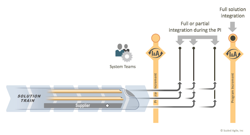
  • Figure 9. Cadence and synchronization enable frequent integration

It is a common myth that solution builders with longer lead time items cannot integrate frequently and therefore cannot apply Lean-Agile practices. Although some teams may not contribute to the end-to-end solution as frequently, they still add new knowledge every iteration through prototypes, simulations, and other experiments. Many disciplines use models to learn faster, possibly at a lower fidelity, before building the final product. Models have many representations, ranging from simulations for hardware, to component-level test doubles/mocks for software, to wood mockups for mechanical domains.
Models can also support end-to-end integration to demonstrate complete or partial system-level functionality. Development boards can be wired together with breadboards and significant IT components can be proxied with test doubles. Figure 10 shows the desired result of continuous integration across the entire solution train with frequent contributions from all solution builders. How frequently solution builders update these models is another economic tradeoff. While there are costs to fabricating the next circuit board, enhancing a simulation, or updating a test double, there is an (often ignored) cost of delay to learning from better fidelity models. This is the same economic relationship as shown in Figure 8 but contrasting the cost of updating models (vs. investing in integration) and the cost of delayed learning.
  • Figure 10. Frequently integrate an end-to-end solution

Continually address compliance concerns
Many large solutions have unacceptable social or economic costs for failure and are often subject to regulatory oversight and compliance requirements. To help ensure quality and reduce risk, organizations operating under such regulations rely on a quality management system (QMS) that dictates practices and procedures. Traditional QMSs were created before the Lean-Agile movement and were based on the traditional approaches already discussed here: early commitment to an incomplete specification, detailed work-breakdown structures, and document-centric, phase-gate milestones to track progress.
A QMS ensures compliance with several types of non-functional requirements (NFRs), including regulatory, statutory, industry standards, business constraints, and enterprise architectural goals. Collectively, these NFRs are validated through compliance activities, which appear in a variety of automated and manual processes. They provide continuous evidence of compliance and the associated quality results. A lean enterprise’s QMS defines this flexibility through practices described below:
Summary
Our dreamers will continue to dream big. After all, organizations must continue to innovate and invest in big ideas to remain competitive. Lean enterprises are adept at building large solutions that are optimized for fast innovation, learning, and adaptation. This article presents a new set of practices, based on the fundamental Lean-Agile principles necessary to drive the development of large solutions in the lean enterprise. SAFe ARTs provide the foundation to coordinate large teams-of-agile teams. These principles show how to scale and produce solutions faster, more predictably, and with a better fit for use, fit for purpose, and quality outcomes.